Tektronix 2465 300MHz Quad Channel Oscilloscope
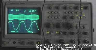
Output of Eico 324 RF signal generator with 500Hz (1/1986µs) AM modulation. Nice distorted sine wave? It's not the Tek.
After a bunch of debug and heartbreaks I finally repaired my Tektronix 2465 digitally assisted analog oscilloscope.
Specifications:
Introduced 1984
300 MHz bandwidth, full analog scope with digital controls
Graticule is embedded in CRT face
Digital assistance with 6802 CPU, uses ER1400 EAROM to save settings
4 input channels (two general purpose, two DC coupled 0.1 or 0.5V/div only)
Internal selectable termination on general purpose inputs
X and Y axis measurement cursors (must be in calibrated modes (detents) for it to work, else it will give a percentage of scale)
X/Y/Z mode (channel 1 is X axis,
other three channels can be used for independent Y axis.
Z axis input is on the rear - with it, it's possible to show raster images!)
10x magnification mode to expand fast signals
Sweep from .5s to 5ns/div
Delayed/Dual sweep mode to see parts of a waveform
Adjustable trigger level with AC/DC/HPF/LPF/auto coupling, ±slope,
trigger on selected channel
I was wondering about trigger inputs as even my Vu-Data has a input to trigger the sweep, but then I finally realized any of the 4 inputs could be used as a trigger. Thus you have to sacrifice inputs if you want external triggers.
I had acquired this from a Hamfest where the original owner abandoned it. It didn't really show any signs of life other than lighting LEDs. Apparently an attempt was made to repair it but it was not complete. So I tried to complete it - however a terrible mishap happened.
The lucky part is that people have scans of the service manual about everywhere. This helped immensely as it shows how the scope should work. However the unlucky part: Apparently the attempt at repairing the scope used a 2440 tube. While the 2430, 2440, 2445, 2465 and related scopes all use the same 154-0850-001 CRT (2467 uses a micro channel plate CRT so a bit different...), using a 2440 tube unfortunately has unintended consequence: the pins on the tube are bent for the 2440. I had tried to bend them back as little and carefully as possible, but this resulted in catastrophic failure. I cracked the tube and still did not bend the pins far enough causing the pins to short against the shield. Double Whammy that I didn't know until much later :-( after extensive debug.
The symptoms of the cracked CRT was extremely subtle. It seemed to display stuff at first but the -15V fuse burned and I assumed the HVPSU croaked.
After a bit of experimentation including incorrectly replacing the LM1458 on
the HV board and many desoldered parts to probe the "flyback"
(which isn't really a flyback as there's no horizontal flyback signal),
I just could not conclude the HVPSU as bad -
it looked all hunky-dory to me. So I went and found the
getter spots on the CRT which required CRT removal - yep, it's toast.
Woe be me...
Normally I would give up on most devices that require a new
CRT as it's usually the most costly device in an oscilloscope or monitor,
but I ended up going ahead and getting another CRT.
This time from a 2445 which matches the form factor and thus no bent pins.

Oh heartbreak! Why doesn't it work after replacing the most expensive part!
At least the high voltage came up just fine, confirming my suspicion that
the PSU was still mostly working.
With the new CRT in, it then showed the next fault: I found out the short against the shield during testing with the bad tube had fried the vertical output amp IC, U600 155-0237-01. So I had to buy another one of those too. I guess the only positive way to think about things, at least U800 154-0241-01 is still good. Now that would be a horrible catastrophe as U800 is treated like gold with so many of them failing in the field...
Anyway, after another few days, receiving the new part, and replacing U600,


As in the service guide, use XY mode to show a single dot... DOT? You mean
LINE?
Oh the horrors, still broken :( I was really depressed at this point after
a whole bunch of things happening at the same time. Anyway, other than the
slight Y smearing (which turns out to be a bad astigmatism setting)
I had a weird horizontal smearing issue that I simply
could not fix by mucking with the focus and astigmatism controls.
I debugged it down to a burned out U1890 (Tektronix part number 156-1191-01)
on the high voltage board,
and luckily I had a spare new old stock identical-to-original LF353 on hand,
though one of the used TL082 pulls I had probably would have worked fine.
Tektronix really did a silly hack here and required a JFET op amp here.
 People should not be building RC delays for 8 minutes, even in 1980!
Tektronix used a 100MΩ resistor (brown black PURPLE gold!
I've never seen a PURPLE multiplier resistor band before!)
and a low leakage 1µF capacitor to
build a ridiculous 8 minute delay (to hit ~95% rail) with a low leakage
JFET amplifier. Oddly enough the parts list indicates a TL072ACP3 here.
People should not be building RC delays for 8 minutes, even in 1980!
Tektronix used a 100MΩ resistor (brown black PURPLE gold!
I've never seen a PURPLE multiplier resistor band before!)
and a low leakage 1µF capacitor to
build a ridiculous 8 minute delay (to hit ~95% rail) with a low leakage
JFET amplifier. Oddly enough the parts list indicates a TL072ACP3 here.
Anyway, after adding a machined pin socket, replacing the op amp with a
new one, and then re tweaking the potentiometers (after modifying them in
a previously futile attempt at focusing), the scope now appears to
be fully functional once more.

"Diagnstic." (Saving a few bytes of RAM or
making it all fit on one 32 character line, Tek?) Alas, all diagnostics passed!
(though these are only computer related diagnostics, does not have anything to
do with analog signal path)
Anyway, it's a a few and far in between victory at last!

Above, out of my Eico 324 signal generator trying to light up the screen with
traces, and the cursors measuring the signal peaks, 134.5mV p-p. Note that
I'm using a 1x probe which would load down the signal generator immensely.
It looks like its Y alignment is still not quite perfect,
probably off less than a degree or so.
Even with that fault, this scope now completely trumps the Vu-Data PS941B
scope that I used to fix this Tek, minus size and simplicity.
Alas I still need to get an even more complicated digital scope someday.
In case anyone's wondering, all pictures were taken WITH the blue filter in place. Beats me why some of the pictures show up greener or bluer than the others, perhaps it's due to the light created by the CRT tricking the camera's auto brightness compensation or perhaps it's due to ambient lighting (which isn't necessary when the screen is lit from lots of traces). Didn't notice the color shift until seeing these pictures.

I got the Tektronix 2440 afterwards, and here's both.
The 2440 does not have the blue filter like the 2465.
I'm thinking about making/adding one.