 12-position switch partially disassembled: shaft: rotation bracket, nut, two
channel locks. Note how they feed into holes on the switch body to prevent
use of those channels.
12-position switch partially disassembled: shaft: rotation bracket, nut, two
channel locks. Note how they feed into holes on the switch body to prevent
use of those channels.
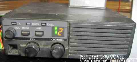
The TK-810 is an old land mobile radio service band FM radio.
It's now considered obsolete due to FCC rule change for narrowband.
However, the hope is that it can still be reused for 70cm amateur radio.
Service manual data swiped from an ebay post:
Frequency range: 450-470MHz (TK-810-1, TK-810L), 470-490MHz (TK-810-2), or
490-512MHz (TK-810-3). As ham frequencies are 420MHz to 450MHz
this radio is not usable as-is for amateur radio.
The TK-810-1 and TK-810L support FRS/GMRS frequencies, and passes FCC rules part 95.
Channels: 4
Channel spacing: 25KHz (PLL step of 12.5KHz)
Voltage: 13.6V negative ground; TK-810L specced at 13.8V
Current drain: 0.45A standby, 8A transmit. TK-810L drains 3.5A for transmit
Duty cycle: Receiver 100%, Transmitter 20%
Sensitivity: 0.45µV
Transmit power: TK-810: 5-25W adjustable; TK-810L: 2-10W adjustable
(the two use different output boards and output driver circuit.
Main radio/transmit boards are the same.)
Slide off rotation bracket if it's still on the switch (the metal shim with two ears bent towards the FRONT of
the radio that mesh with two holes in the front panel - don't lose it, it may
still be in the front panel!)
After pulling the switch, remove the nut on the switch and set aside.
At this point you should be able to remove the detent blocks which
look like washers with a peg sticking into one of the 12 holes on the switch.
There will be two of them, unless your radio was originally locked to 11
channels. Pull them straight off and replace the nut.
Reassemble, and now the radio can be set to all 12-channels now! However
there will no longer be a stop to tell you when you reached channel 1 without
looking at the display.
Note that now you will probably want to deal with the display at the same time.
I found it easier to remove all the boards from the front panel (4 self
tapping screws for the PCB and the nut on the volume control).
Don't lose the plastic button extenders for the two pushbuttons,
they may fall off the switches. The display PCB
on the front of the unit are held in by plastic hooks on both sides - be
careful spreading them apart to remove the display board else they may break.
If one or both break, game over. New front panel needed.
The display sits flush to the gray front filter. If you're using discrete LEDs
like I'm using in the first photo, you'll need to make sure they do not extend
past the height of the 7-seg display. I ground off the tops of the LED to make
them fit.
The OEM for this display is the LA301DB:D15 but believe a 2mm pitch 10-pin
similar to HP/Agilent/Avago/Broadcom HDSP-U411, which should still be available,
will fit if you want it to look more natural rather than a hack.
 All programming is done through a connector on the top of the front face board,
underneath the external case panels. An 8 pin card edge slot provides
connection to a 93C46 1Kbit EEPROM which holds all programming information.
Kenwood expects the use of their tool, the KPT-20, to program the channels.
It does NOT support RS-232 serial programming through the microphone jack
like some of the newer TK-series radios.
All programming is done through a connector on the top of the front face board,
underneath the external case panels. An 8 pin card edge slot provides
connection to a 93C46 1Kbit EEPROM which holds all programming information.
Kenwood expects the use of their tool, the KPT-20, to program the channels.
It does NOT support RS-232 serial programming through the microphone jack
like some of the newer TK-series radios.
Example: if you see "83 89" in your EEPROM and you want to calculate the frequency being used. First check if you need to byte swap. The last bytes in the EEPROM image is a clue whether it was read 8 or 16 bit. If it reads "R820N1" in ASCII (versus 8R021N - btw I don't know if this is a magic word or actually means something), the frequency bytes need to be swapped to 0x8983. Now convert 0x8983 to decimal: 35203. Then multiply 35203 by 12.5 (KHz) and add 21400 (KHz; 21.4MHz), resulting in 461437.5 KHz.
To program your desired frequency, just go backwards. Example: if you want to program 446.000MHz - First convert to KHz: 446000 KHz. Then subtract the IF of 21400 KHz, 446000-21400=424600. Then divide by the channel spacing: 424600/12.5=33968 which becomes the PLL divider. Converting to hex it becomes 0x84B0. Now byte swap for little endian if necessary depending if your programmer deals with bytes or words, in my case it would be bytes: B0 84 -- and this now is what needs to be programmed into the radio to get 446.000 MHz. You'll need to repeat B0 84 at word location 0x1 to transmit/receive simplex. Note that this example is probably not a good example to use because this frequency falls below the lowest possible frequency of a stock TK-810 (450MHz to 512MHz) but should work with a bit of tweaking.
In any case, the other 11 channels simply follow in sequence pairs (receive, transmit) for the next 44 bytes in the eeprom. The 12 channels' worth of receive/transmit frequencies take up 12 channels times 2 (one receive, one transmit) times 2 (two bytes per word) equals 48 bytes of data, thus filling locations 0x00 to 0x2F.
Note that this is still a work in progress as it's unknown if other
data is encoded into the eeprom.
It seems that CTCSS/PL codes are likely hardcoded on the tone board
DIP switches installed in the top of the unit (KQ-7 CTCSS option),
and the same code used for all channels, both transmit and receive.
The eeprom from 0x30 to 0x79 appear to
be unused, and the last 6 bytes show up as R820N1 just like the TKR-820.
I don't know if this will be the case if you have the KMS-4 Kenwood
Multiple Signalling board, the data may be stored in the eeprom as well.
The CTCSS tones are stored on a different chip, not this specific chip for the
transmit/receive frequencies, and it appears the rest of the unused portions of
the chip is indeed unused/wasted.
 I was a bit dismayed that I could not receive 447MHz stock, despite being
only 3MHz under the supposed 450MHz lower frequency.
However I have found that it's possible to change the passband a bit by
turning the inductor coils on the radio board. These are the 6 flat
screw-slotted metal shielded inductors towards the rear of the main radio
board that rests underneath the tone board. After futzing with them a bit,
I was able to receve below 450MHz. Note that this is a passband, reducing the
low end will also reduce the high end receiving, so don't expect to be able to
widen the pass band much at all.
This is the analog portion - the EEPROM changes to program the PLLs
are still necessary of course.
I was a bit dismayed that I could not receive 447MHz stock, despite being
only 3MHz under the supposed 450MHz lower frequency.
However I have found that it's possible to change the passband a bit by
turning the inductor coils on the radio board. These are the 6 flat
screw-slotted metal shielded inductors towards the rear of the main radio
board that rests underneath the tone board. After futzing with them a bit,
I was able to receve below 450MHz. Note that this is a passband, reducing the
low end will also reduce the high end receiving, so don't expect to be able to
widen the pass band much at all.
This is the analog portion - the EEPROM changes to program the PLLs
are still necessary of course.
| Programmer pin | 93C46 pin | Description |
|---|---|---|
| 1 | 4 | DO output TO KPT-20 |
| 2 | 3 | DI input FROM KPT-20 |
| 3 | 2 | SK/CLK |
| 4 | 1 | CS/Chip Enable |
| 5 | n/c | not connected |
| 6 | (8) | Reset TK810 CPU - Enable Programming |
| 7 | 5 | Ground |
| 8 | n/c | not connected |
As far as I know now, CTCSS/PL is done by a board installed on the top board
position. The board I have is the cheaper KQT-7, the Kenwood Quiet Tone.
There are 6 DIP switches that enable most
of the standardized 38 CTCSS tone frequency codes.
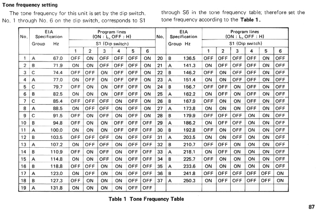
The KQT-7 uses the same CTCSS code for all channels, both transmit and receive.
Microphone pinout (6P6C RJ-12 for electret, 6P4C RJ-11 for dynamic):
| Pin | (Ignore) | Usage |
|---|---|---|
| 1 | blw | Monitor (connect to PTT when off) |
| 2 | gr | Microphone (10K pulldown, couple with capacitor)coupled |
| 3 | orw | Microphone ground |
| 4 | or | PTT |
| 5 | grw | PTT GND |
| 6 | bl | Electret Power-13.2V (110 ohm to 78L06 to 680 ohms to transistor collector, 56 ohms emitter bias) |

If you would like me to socket your 93C46 so that you can program it at
your whim in the future, and do
initial programming for your TK-810/TK-810L,
this service will be available for a fee:
 Send only the base radio, do not send microphone, brackets, or any accessories
as they may be lost.
You may send just the controller board with the EEPROM, for a
$5 return shipping discount, but of course you will need to do tuning.
Send only the base radio, do not send microphone, brackets, or any accessories
as they may be lost.
You may send just the controller board with the EEPROM, for a
$5 return shipping discount, but of course you will need to do tuning.
The TK-810L (FCC ID ALH-9TKTK-810L-1) is certified for FCC rules part 15B, 22, 74, 90, and 95 along with the TK-810-1. The TK-810 -2 and -3 were not part 95 certified. Note that tuning will cancel certifications. Each of the TK-810s are only good for 20MHz band spread, so it's impossible to use, say, 440MHz and 480MHz without hardware tuning every time you switch to each frequency.
I can add receive-only programming if desired, there are no restrictions for this programming as long as it's valid for the 70cm band.

