Two color LEDs
Two color LEDs are LEDs that can glow more than one color. Their body color
are usually translucent white. They can have two or three pins. Here we'll
focus on the three pin variety - the two pin variety requires a different, more
complicated driver circuit to work right.
The three pin unit also contains two distinct LED chips in it. One will glow
one color, and the other, some secondary color. Usually one is green and
one is red, but a orange+green one has been seen before. If both LEDs are
turned on, the color mixing you'd expect will occur, and a orange/yellow color
is emitted. Both chips share one pin, the 'common' pin.
PC/Computer LED Use Theory
LEDs are used to display status. They can be your hard disk light, power,
turbo (if you have an old one), and many many other purposes. You'd have
hundreds of possible LED stats, but reduced to a select few that are important.
Reduced to so few, that only a handful is on the front of your CPU case.
So, why not use these multicolor LEDs? For instance, my case HDD LED glows
red when IDE is being accessed, and green when SCSI is.
LED Drivers
How are LEDs turned on and off? There are transistors of some sort switching
the LED ON and off. It could be any kind, bipolar or metal oxide field effect.
This transistor is connected into series with the LED to switch it 'on' and
'off'. To properly turn an LED on and off rapidly, a common emitter/common
drain circuit is used. So a PNP BJT transistor could be used to "turn power
on" or a NPN to "turn ground on" in layman's terms.
Not getting into device physics, it's usually the "NPN" or "N-channel" device
that's used to power LEDs because of their ability to conduct current in
minimal amount of area (due to electron mobility). So, *most* LED circuits
are powerred this way - power to a resistor to the LED to the collector of an
N-channel MOSFET or NPN transistor. There could still be a p-channel or PNP
transistor there but it won't be used.
The problem
Now, we mentioned that it could be designed either way, we could have the
situation where the two circuits are driven differently, so there would be
hard to hook up a shared terminal device. There is another issue - most 3
pin LEDs are invariably common cathode devices! So if the circuit is using
NPN transistors to power the circuit, you're out of luck.
There is a good scenerio, where both circuits use complimentary drivers and
reference to ground. This case you can just use the 2-color LED directly.
This, however is rarely the case! :( And who knows how your output circuit
is designed. So, the following circuit will totally eliminate any guesswork
involving output drivers and reference points.
Just hook it up (You need power) and go! That's it!
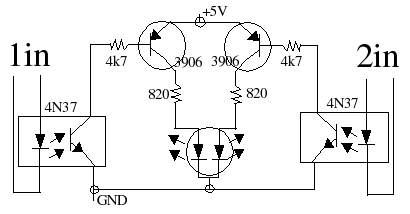
Parts list:
Circuit board
Two 4N35/4N36/4N37/H11A1 optoisolators - to emulate the LEDs
two 4.7K ohm resistors
two 820 ohm resistors
two 2N3906 transistors
one dual color 3-pin LED
connectors...
Theory of operation: The LEDs in the optoisolators now light up when the
output is being accessed. The circuit will then use that output to light the
LEDs.
With a common anode device, the two transistors can be omitted, however, you'll
get better brightness with this circuit as the saturation current of the 2N3906
transistors is higher than of the optoisolator transistors.
Copyright (c) 2004 blc
Permission is granted to resell this circuit as long as you put credit where
it's due.
2004May02-Found error in schematic, fixed (Transistor Collector/Emitters
drawn incorrectly. I wish I had a good sch capture program, ooimpress is all
I got).